Industry trends indicate that an active Ethernet approach may become the architecture of choice for fiber-to-the-home (FTTH) deployments. Although there are many contributing factors, one very obvious reason is the desire for additional bandwidth to potentially deliver more features to the end customer. While there  can be additional costs associated with this architecture, typically the labor cost for physically burying a 24-fiber outside plant (OSP) cable or an 864-fiber OSP cable in the ground is virtually the same. Even if a service provider plans for a passive optical network (PON) approach today, building a network with dedicated fibers to each subscriber opens a migration path toward an active approach in the future.
This article addresses considerations for cabling and cable management between the optical distribution frame (ODF) and the active electronics in the central office/headend (CO/HE) when deploying active Ethernet. Deployment scenarios typically differ, so there are several options available for connectivity and cable management 每 each with its own advantages and disadvantages. In general, there are three connectivity methods 每 multi-fiber cable assembly, patch cord, and a tie panel approaches. The method selected by the service provider will determine how installation, operation and maintenance issues are handled.
Connectivity Choices
Typically, an active Ethernet FTTH system deploys a dedicated fiber from the electronics in the CO/HE to each subscriber at the customer premise. This requires the management of a significant number of fibers within the CO/HE and presents the service provider with the issue of how to best connect the active equipment to the OSP. These fibers not only require effective management during initial deployment, but also during day-to-day operations.
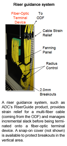
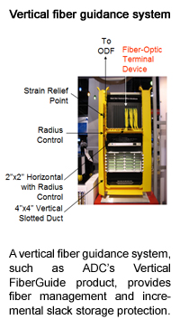
Numerous options exist for connecting the ODF to the active equipment within the CO/HE, but four connection options are typical 每 individual patch cord, a 900-micron style breakout cable, a 1.7 mm style breakout cable, or a tie panel. In terms of fiber management, today*s optical raceway systems, vertical fiber guide and riser guide systems are designed to protect and route fiber cable assemblies to and from fiber splice enclosures, ODFs, and terminal devices. With fiber densities increasing in the CO, the need for providing cable strain relief, and proper incremental slack storage, have never been more important.
Individual Patch Cords
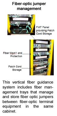
Using individual patch cords provides the most flexibility for interconnecting equipment, enabling technicians to make moves, additions and changes with relative ease. However, any time jumpers are implemented in single mode  applications, the jumpers are factory-manufactured (thus, typically longer than necessary) and require slack storage. The use of individual patch cords provides a large degree of flexibility when storing excess slack, discretely locating jumpers or when troubleshooting circuits.
There are three primary areas for slack storage using individual patch cords. Slack storage can be at the ODF, inside an overhead raceway system or at the active equipment rack. At the ODF, slack is stored in a fiber-optic storage bay or panel. The optical raceways typically use in-line storage areas, and the active equipment should have a vertical management system or storage panel for dealing with slack storage. When storing slack at the active equipment, it is recommended to allow a five-inch space between active bays for patch cord slack storage or breakout cable service loop storage.
Breakout Cables
Although individual jumpers provide the highest flexibility for interconnecting equipment, active Ethernet architectures with dedicated fiber requirements may be tasked with turning up multiple customers simultaneously from a single active equipment blade. In these cases, it may be much easier to run a single multi-fiber cable between the active gear and the ODF, and then break out the individual fibers at the active equipment shelf. Each breakout cable must have 1.7mm/2.0mm up-jacketed fibers at the active end to provide adequate fiber protection.
It should be noted that having multiple fibers within a single sheath makes length measurements much more critical between these two areas.
There are typically two styles of breakout cables 每 900 micron and 1.7 mm 每 and both have certain advantages over the other, depending on the application. Because both are typically riser rated and contain multiple fibers in a single sheath, a dedicated fiber raceway is not necessary between frames. Breakout cables install directly into the rear of the ODF, and the 900-micron cable has the advantage because of its smaller outside diameter that contributes to less pile-up in the bay and overhead areas. Both breakout styles have higher initial capital expenditures when compared with the individual jumper approach, but requires less overall labor for installation.
Since there is typically a standard breakout length among all the individual fibers at the active equipment end, provisions must be made for storing incremental slack from the breakout to the active equipment blade. Dedicating space between the bays and the use of a vertical management system enables proper strain relief and effective service loop storage that is necessary for fanning out fibers to different blades within the active equipment shelf.
Although the 1.7-mm style breakout cable offers some of the same advantages as the 900-micron option, it has a larger outside diameter and is better protected at the ODF. It*s important to note that because of the 1.7-mm style breakouts, the service loop may not fit into the back of the ODF panel. As a result, a slack storage solution at the ODF is needed, along with a slightly longer ODF breakout length
Tie Panels
Another connection option is to place an intermediate tie panel either in the active equipment bay or within the same lineup to serve as a patch point. A single, double-ended intra-facility cable is placed between the ODF and the fiber  termination tie panel. Ideally, a multi-fiber cable with 900-micron sub-units can be used between the ODF and the tie bay. This cable is easily terminated without the need for an extra slack storage solution. Patch cords are then run between the active equipment and the front of the tie panel.
Adding this intermediate fiber termination panel provides a measure of flexibility by having relatively short patch cord connections between the active equipment and the tie panel and a permanent connection between the tie panel and the ODF. However, there is a higher cost associated with this approach because of the tie panel and additional cabling.
Horizontal and Vertical Management
Fiber management must always be weighed as a major consideration when designing networks within the CO, both between the equipment racks and within the active equipment. For the overhead pathway between the ODF and active equipment areas, the typical choices are either a ladder rack configuration or fiber raceway system. The ladder rack system is particularly suited for larger multi-fiber cables 每 such as 24-fiber or greater fiber count cables. For individual patch cords or smaller multi-fiber cables, a flexible, easy-to-install, durable fiber raceway system is the best choice for the greatest fiber protection and accessibility. It should be noted that best practices dictate that all fiber cabling be run through a dedicated raceway or ladder system, separate from copper cabling
Cable management within the active equipment bay is an important factor to consider in the planning stages, since many active Ethernet system manufacturers have little or no fiber management outside their equipment footprint. Built-in vertical or horizontal management may be missing entirely from some products altogether. That puts the burden squarely on the shoulders of the service providers to ensure proper space is allocated within the active frame bays for managing excess fiber slack.
Today*s networks require much larger amounts of fiber than ever before. These higher fiber densities need fiber frame systems that can handle large amounts of fiber from the active electronics.
As fiber densities continue to increase, service providers must seek out equipment that is built to handle more fiber terminations within a smaller footprint. With added density, there are also additional fiber management issues and concerns. Installing racks and bays, along with fiber raceways and riser guidance systems that help to protect and manage large amounts of fiber, will create a solid fiber management system 每 one that will reap benefits well into the network*s future.


